P14 User Manual
How to collect your imaging data.
High-Throughput Tomography (HiTT) on P14
We have developed a high-throughput workflow for imaging of biological tissue. As a result, there are defined ways of preparing your samples. The following section provides comprehensive details regarding the imaging parameters and on-site image acquisition protocols.
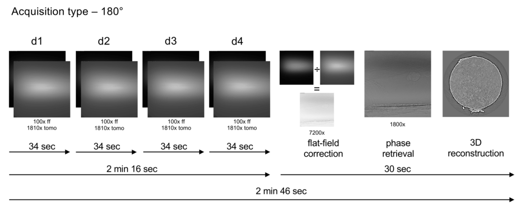
The acquisition protocol consists of acquiring a tomographic dataset of the sample at each of four different sample-camera distances. Phase retrieval from this data is performed using the “holotomography” approach, after which tomographic reconstruction is performed.
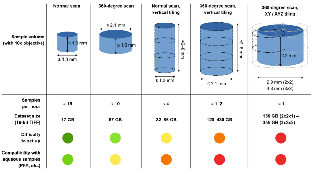
For suitably small samples (at most 1.3 mm diameter and 1.0 mm height), a single 180-degree tomographic scan is performed at each distance.
For somewhat larger samples (up to 2.1 mm diameter, 1.0 mm height), the system can be set up to perform 360-degree, off-centre tomography. Samples with a greater height or diameter can also be scanned by repeatedly performing region-of-interest tomography (“tiling” acquisition) and stitching the resulting 3D data.
This is easy to do if tiling is only required for the vertical direction, but tiling in multiple dimensions is more complex and also results in the generation of a large amount of data. Furthermore, samples in aqueous solution tend to generate gas bubbles in the synchrotron beam, which often affects image quality. The probability of bubbles appearing increases with the length of the scan, and thus the number of tiling steps.
The figure below gives a qualitative comparison of the available acquisition techniques.
P14 is an undulator beamline, which uses a double-crystal monochromator to generate monochromatic radiation of photon energies between 8 and 32 keV. Energies typically used for imaging are 18 and 23.5 keV, selected depending on the dimensions and composition of the sample. Energies between 26.5 and 32 keV are available on special request.
The size of the beam at the position of the sample is about 1.3 mm x 1.0 mm (width x height), which is the primary limitation for the size of imaged samples (see also the section “Detection system” below).
The MD3 diffractometer is used as a rotation stage for tomographic imaging. The rotation axis is oriented vertically, and the samples are mounted downward, i.e. “hanging” from the attachment point. The sample mount is based on the SPINE magnetic sample holder developed for macromolecular crystallography (MX). The diffractometer features a visible-light microscope which is aligned with the X-ray beam that enables, in combination with a graphical user interface, convenient alignment of samples with the beam before enabling X-rays. Samples can be mounted manually or using the sample changer described below.
We use an Optique Peter X-ray microscope in combination with a PCOedge 4.2 sCMOS camera (2048 × 2048 pixels, 6.5 μm pixel size, max. 100 Hz frame rate) and an LSO:Tb on YbSO scintillator (thickness 8-10 μm). The microscope features three objectives, providing 4x, 10× or 20× magnification. For 4× and 10×, the effectively usable field of view is however limited by the extent of the beam (about 1.3 mm horizontal × 1.0 mm vertical).
For the majority of experiments, we recommend the use of the 10× objective, but this can be discussed at the time of proposal submission and/or in the run up to your beamtime.
| Objective | Usable field of view (H x V) | Pixel size |
| 10× | 1.3 mm × 1.0 mm | 0.65 μm |
| 20× | 0.67 mm × 0.67 mm | 0.325 μm |
| 4× | 1.3 mm × 1.0 mm | 1.625 μm |
The user primarily interacts with the beamline via the MXCuBE graphical interface in “imaging” mode. This software allows sample centring, adjustment of a wide range of setup and acquisition parameters, and starting image acquisition. Manipulation of various motorised stages required for aligning the setup and other tasks can be performed via a second graphical interface, or alternatively, directly interacting with the TINE beamline control system through a command line interface. Additional tools exist for use by beamline staff for diagnostics and specialised tasks.
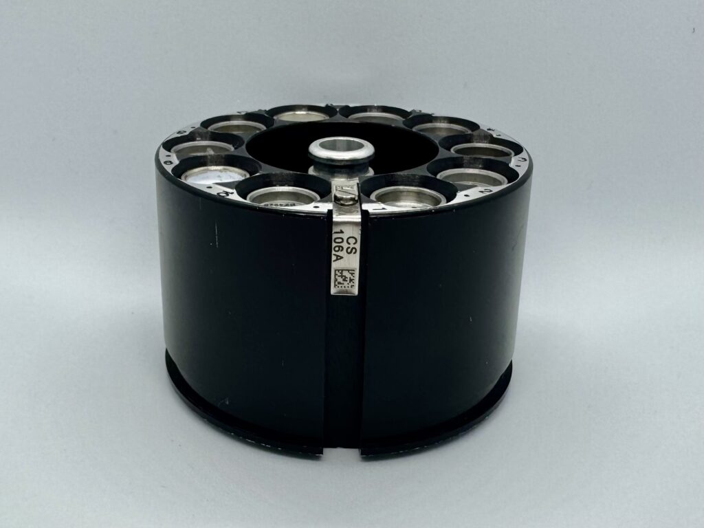
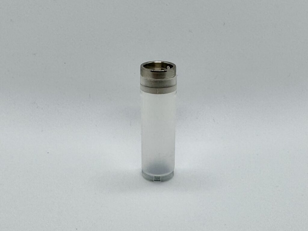
At P14, we use the SPINE system for mounting samples, which is widely used in macromolecular crystallography (MX). This system consists of:
We commonly use 3D-printed adapters to attach samples to the SPINE bases. The MARVIN sample changing system (see below) is designed around the SPINE system.
A reasonable number of SPINE bases and caps can be obtained from us upon prior request. For larger experiments with big sample cohorts, SPINE bases and caps can be acquired here:
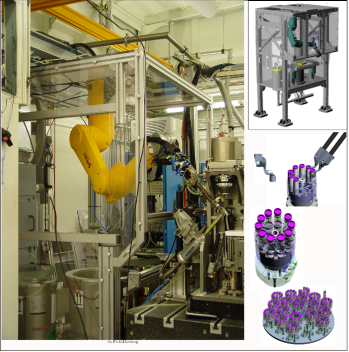
The “MARVIN” sample changing system is available for the transfer of samples from storage to the diffractometer for imaging, and is controlled via the MXCuBE interface. The storage has a capacity of 17 pucks, i.e., up to 170 samples.
The acquisition protocol consists of acquiring four tomographic datasets of the sample at four different sample-camera distances (73–92 mm).
After collection, the beamline compute cluster automatically performs flat-field correction, “holotomography” phase retrieval, and 3D reconstruction of the data (using the “gridrec” algorithm). The processing time is one minute for a standard scan, and the results can be viewed immediately afterwards. If tiled acquisition is performed, the individual datasets are automatically stitched as soon as reconstruction is complete. This usually also takes only a few minutes.
How to collect your imaging data.
Synchrotron Radiation, 31(1), 186-194 2024
DOI: 10.1107/S160057752300944X